- S6.8.6
-
Edge regularity
- Where the existing surface is a bound material, the edges of excavations at the binder or surface course level must meet the following requirements:
- Micro trenches must comply with S6.6.
- Large diameter core excavations must comply with S6.7.
- For all excavations other than micro trenches and large diameter cores, all edges must be essentially straight, smooth and vertical to enable compaction of the reinstatement materials. The preferred methods for this are by saw cut or trimmed by saw.
- Overlapping edge cuts and corner cut outs should be kept to a minimum. All cuts extending into the existing surface must be filled with a flexible bituminous sealant.
- Internal corners should generally be 90° or more. Where internal corners are less than 90° then compaction equipment must be suitable for achieving compaction in the corners.
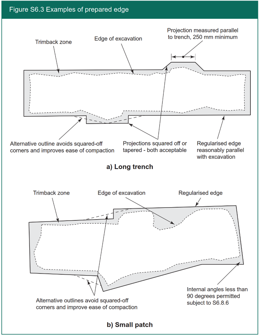
- There is no requirement to trim the sides of trenches solely to provide a uniform width provided that individual projections are not less than 250 mm long when measured parallel to the notional centreline of the trench. See Figure S6.3 (a).
- There is no requirement to trim small openings solely to provide a square or rectangular shape. Any shape, having no projection less than 250 mm long, may be considered to be regular. See Figure S6.3 (b).
- Where the existing surfacing material is sound at the corners of an excavation, there shall be no necessity to cut out to a corner; a regular chamfer may be preferable.
- The trim-line may be confined to the surface course provided the lower layers have not been damaged. In this case, the surface thickness must match the existing. If the lower layers have been damaged; trim line must include all layers and these must be fully reinstated following the requirements of this Code.
- Where the existing surface is a bound material, the edges of excavations at the binder or surface course level must meet the following requirements:
- S6.8.7
-
Edge sealant
- For all excavations other than micro trenches, all edges must be adequately prepared before applying edge sealant. This requires:
- the removal of all excess water from the cut face.
- all bound vertical edges to be free of contamination, loose material, slurry or dust, with any cut face of the aggregate in existing layers clearly visible.
- any additional steps detailed in the manufacturer’s instructions to be followed when using proprietary products.
- For reinstatement of all excavations other than micro trenches, whether interim or permanent, the top 100 mm at least of all bound vertical edges at surface and binder course levels (and the equivalent area on kerbs and exposed fixed features) must be painted with an edge sealant or prepared with an edge sealing system. No significant splashing, spillage or deliberate over painting of the adjacent road surface is permitted.
- The edge sealant or edge sealing system must comply with the following, if applicable:
- hot bituminous binder must have a penetration of not less than 40 pen;
- hot elastomeric polymer-modified bituminous binder must comply with BS EN 14023 with a penetration of not less than 40 pen;
- if hot bituminous binder is not used, cold applied thixotropic bituminous compound of similar bitumen or polymer-modified bitumen grade may be used, i.e. cold applied aerosols;
- polymer-modified adhesive bitumen strip must have a minimum thickness of 2 mm and must adhere to both cold and warm upstanding edges when the asphalt is applied. The product must be compatible with the material(s) installation process.
- There should be evidence of the use of sealant. Evidence may include visual evidence or quality control records from the reinstatement works.
- For all excavations other than micro trenches, all edges must be adequately prepared before applying edge sealant. This requires:
- S6.8.8
-
Overbanding
- Overbanding may be used in reinstatements, including remedial works (see S12.3.3) to improve durability. If overbanding is used, it must comply with the reinstatement guarantee period.
- Overbanding must be at least 3 mm wide, no wider than 40 mm, and be no more than 3 mm thick at the surface.
- The overbanding system must have a current certificate by a Product Acceptance Scheme. Alternative certification is required to confirm suitability of use of the overbanding product for its in-service use.
- Hot or cold applied systems may be used, subject to the manufacturer’s recommendations.
- Treatments must be black in colour, unless otherwise directed by the authority.
- The minimum PSV for chippings applied to the repair systems is as specified for surfacing (see S2).
- The initial skid resistance must be ≥55 SRV as measured by the pendulum tester using the narrow slider in accordance with BS EN 13036-4.
- Installation and Quality Control Procedures for all systems must be in accordance with the Product Acceptance Scheme certificate for each system and the current Method Statement. The results of all quality control checks carried out on site by the undertaker and quality assurance information must be compiled in accordance with the requirements of the certificate.
- Preparation must be in accordance with the installation method statement and must include cleaning and removal of debris and contamination. The substrate must be dried fully before applying crack or joint treatment.
- Overbanding must not be used as a substitute for edge sealing.
- S6.8.9
-
Proximity to road edges and fixed features
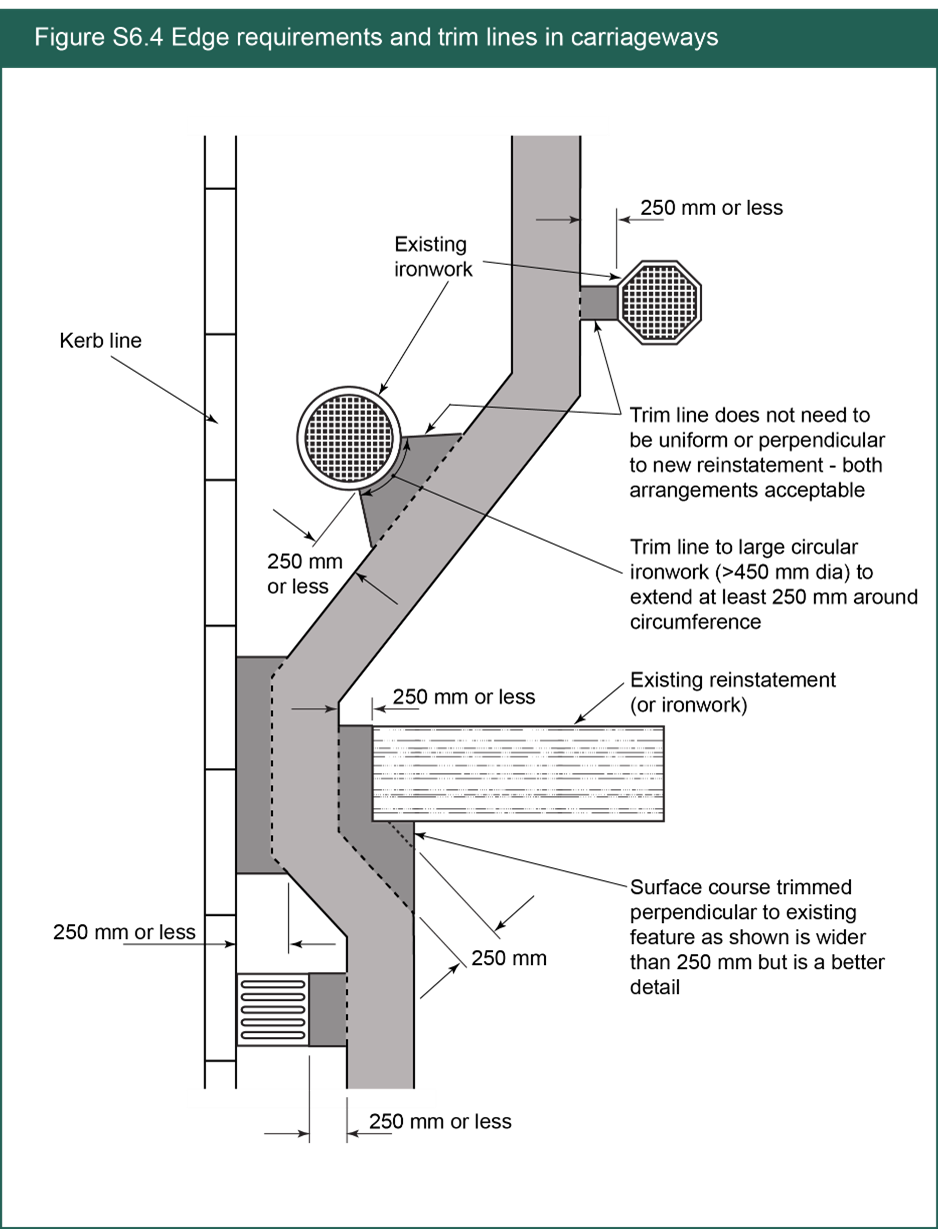
- Where the trimmed edge of any excavation is within 250 mm of the road edge, kerbing, other fixed features or another reinstatement, the trim-line must be extended to the interface with the road edge, kerbing etc. See Figure S6.4.
- The additional reinstatement area required by extending the trim-line may be confined to the surface course provided the lower layers have not been damaged. In this case, the surface thickness must match the existing. If the lower layers have been damaged, the trim line must include all layers and these must be fully reinstated in accordance with this Code.
- Where an existing fixed feature is immediately adjacent to another (e.g. road gully, stop-cock valve cover, etc.) material selection must be appropriate to ensure adequate compaction and surface profile – see S2.2.
- S6.8.10
-
Undercutting
- All bound edges must be fairly smooth and vertical with no significant undercutting, see Figure S6.5.
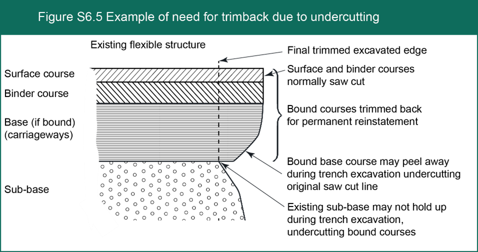
- There may be no need for trimback when undercutting occurs if PMMA is used as sub-base and base. If an FCR or a FSMR (see A9) is used, then consideration of shrinkage during curing must be demonstrated to ensure support of the overlaying structure.
- All bound edges must be fairly smooth and vertical with no significant undercutting, see Figure S6.5.
- S6.8.11
-
Stepped joints
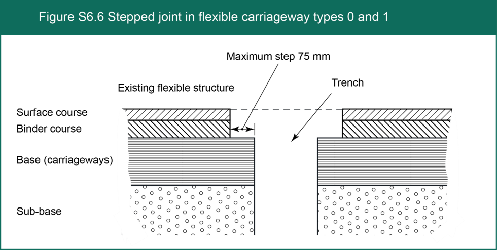
- On Type 0 and 1 roads where it is the custom and practice of the authority to cut-back the surface or binder course to provide a stepped profile, this must be notified to the undertaker. Subject to the agreement of the authority, the stepped joint may be applied to reinstatements in Type 0 and 1 roads subject to the following:
- Large diameter cores, small openings and narrow transverse trenches are excluded.
- The stepped profile must match the authority’s policy subject to a maximum step of 75 mm– see Figure S6.6.
- On Type 0 and 1 roads where it is the custom and practice of the authority to cut-back the surface or binder course to provide a stepped profile, this must be notified to the undertaker. Subject to the agreement of the authority, the stepped joint may be applied to reinstatements in Type 0 and 1 roads subject to the following:
Skip to main content
