Multiple interlocking or closely spaced large diameter cores have the potential to create areas of weakness in the pavement. This will depend on several site-specific factors including location of the core, composition of the pavement, and the coring arrangement. The authority should not withhold the use of multiple cores if it is proven to be common practice.
All measurements between core locations are taken as a horizontal measurement between the two closest edges of the cores.
Coring and removal of the large diameter core
Verticality of the core barrel set up on site and the specifics of the coring plant have an influence on the potential to damage the surrounding surface.
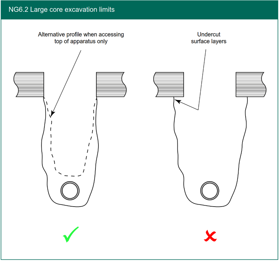
Figure NG6.2 shows a schematic cross section of acceptable and unacceptable excavations. The assumption behind not being able to complete the reinstatement in accordance with S6.7.17 is that there is a risk that compaction will not be achieved if structure has been undermined. This is particularly critical in the zone directly supporting the bound layer adjacent to the core hole. It may be that a suitable flowable material (e.g. PMMA or FCR or A9 FSMR) could be used as an alternative in this scenario.
Materials
When reinstating using the core, the bonding material needs to fill the annular space between the core and the hole to securely bond the core to the existing surface. In addition, the bonding material must be volumetrically stable and resistant to cracking or water penetration.
Backfill and compaction
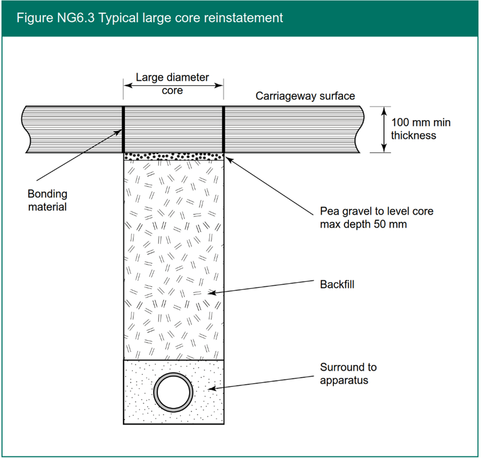
Figure NG6.3 shows typical large core reinstatement using pea gravel for levelling the core during the reinstatement process.
Core reinstatement and bonding
Typical considerations in the Method Statement for a large diameter core reinstatement would include that:
- The core must sit horizontally within the hole, 25 mm below the surrounding carriageway surface with a nominal gap of 7 mm between the core and the hole.
- An alignment clip can be used to aid this process.
- The core is then removed, and a sufficient quantity of bonding material is applied to ensure the 100 mm pilot core and the gap between the core and the hole is completely filled. There must be no visible voids present.
- A satisfactory result is confirmed by the presence of a small amount of bonding material extruding to the surface.
- When suitably cured, the excess material must be removed from the surface and adjacent areas. The reinstated core must be left in an acceptable visible condition. If power washing or similar processes are applied, care should be taken to avoid washing contaminated fluids into drainage systems.
