General
Micro trenches are generally used for major works. Apparatus installed in a micro trench might comprise:
- Mini-ducts, single or multiple, or
- Directly buried cables, single or multiple.
After installation, ducts have cables installed inside them. Cable installation operations should not impact upon the reinstated micro trench. Any surface cracking or other evidence of distress is likely to result in significant overbreak during excavation. In this case it is likely that reinstatement would be required using narrow trenching.
When planning the position of the micro trench, safety and ride quality for cyclists should be considered.
Excavation/cleaning
The method of cutting/excavation used for micro trenching can have a significant impact on the ability to achieve an effective reinstatement. The greatest threat to effective reinstatement is the presence of excess moisture. For this reason, a dry cutting process using a vacuum recovery system for the arisings is preferred.
The minimum combined thickness of courses 1, 2 and 3 above the apparatus has been specified for safety and technical reasons. This includes ensuring a minimum cover of the apparatus to remove the risk of strikes when milling the surface and binder course in maintenance operations.
Subsequent excavation and reinstatement by others
The following sub-paragraphs provide guidance to other undertakers or street authorities where their excavations expose ducts or cables in micro trenches.
During excavation, it is expected that the original reinstatement materials above the ducts/cables (materials 1 and 2 as per main paragraph 4) will be removed.
The exposed duct/cable will require temporary support and protection in the same manner as any other exposed service - a small amount of flexibility in the exposed duct/cable will be apparent at the time of excavation.
It is recommended that the owner of the duct/cable should specify that the exposed length should be sleeved inside split steel ducts at this point.
The steel ducts should be made freely available by the owner, and their use will provide:
- Increased physical protection during these subsequent reinstatement operations;
- Increased service traceability ahead of further re-excavation on future works;
- Increased physical protection during the further re-excavation (as coloured material 1 will not have been reinstated).
Reinstatement of the subsequent excavation will require the careful deposition and compaction of lower layer granular materials, in a similar fashion to current practices when working around other services.
The small amount of flexibility in the exposed duct/cable is unlikely to allow the line and depth of the duct/cable to deviate greatly from its original as-laid position. As a result, some depth of binder course materials will require careful deposition and compaction to the underside of the sleeved duct/cable.
In the same manner, the next lift of the binder course above the sleeved duct/cable will require careful deposition and compaction. However, with the added protection of the split steel ducts, normal compaction should be achieved, again in a similar fashion to current practices when working around other services in the bound asphalt layers.
Installation
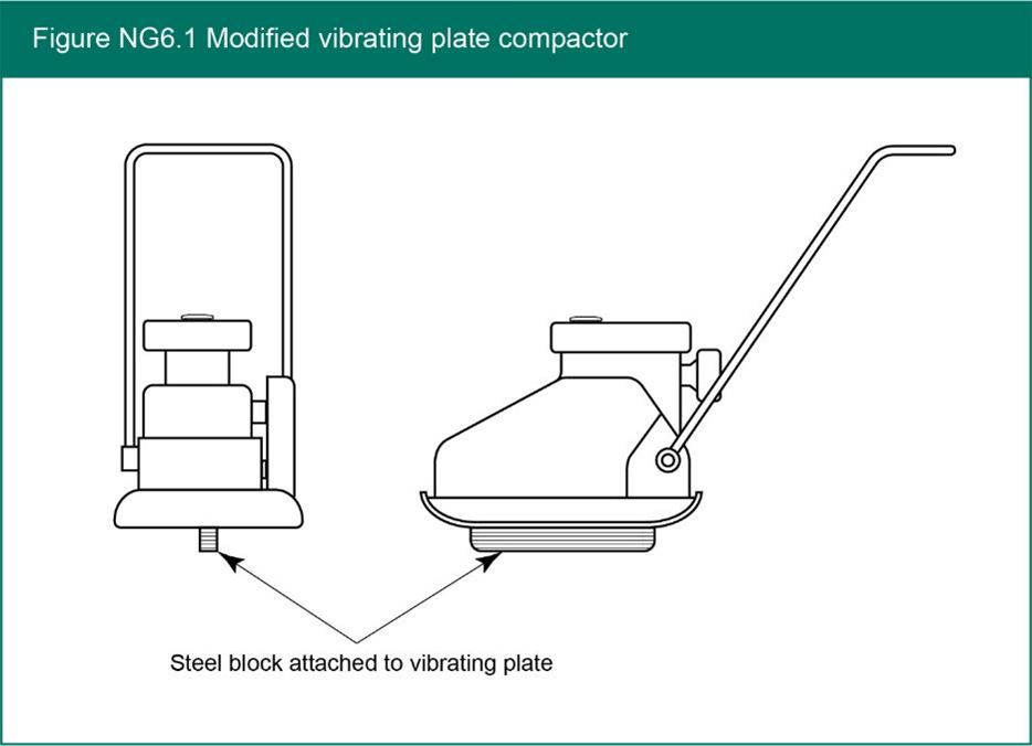
In Figure NG6.1 an example of a suitable compaction tool is shown. This is for guidance only and other modified equipment to achieve compaction may be used.
For course 3, nominal means the approximate dimension by which a material is generally called or sold in trade, but which differs from the actual dimension.
Materials specification
Any alternative materials will be progressed via A9 and potentially then also supported by a Product Acceptance Scheme certificate. Desirable properties include skid resistance of the surface, flowability during reinstatement, adhesion of the product to the reinstatement edges post curing, mechanical performance under loading, volumetric stability during its in-service life and durability (including frost resistance and resistance to water)

