- S7.5.5
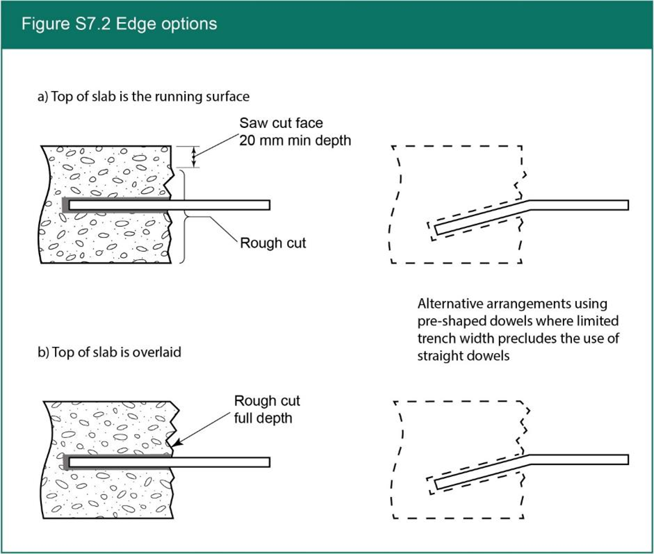
- Where the top of the slab is the running surface, the excavation must be delineated by pavement sawing to a minimum depth of 20 mm. Any unsawn section of the slab may be left rough-cut as long as it presents an approximately vertical surface - see Figure S7.2 (a). For overlaid slabs, the edges should be prepared as detailed in Figure S7.2 (b).
- S7.5.6
- In narrow trenches and small openings (S1.5.3 and S1.5.4) the cut section of concrete may need to be widened to accommodate dowel bar installation or the holes may be drilled at an angle to allow the use of pre-shaped (angled) dowel bars. They must be drilled along the centreline of the exposed faces, to provide a sliding fit for 20 mm or 25 mm diameter steel dowel bars.
- S7.5.7
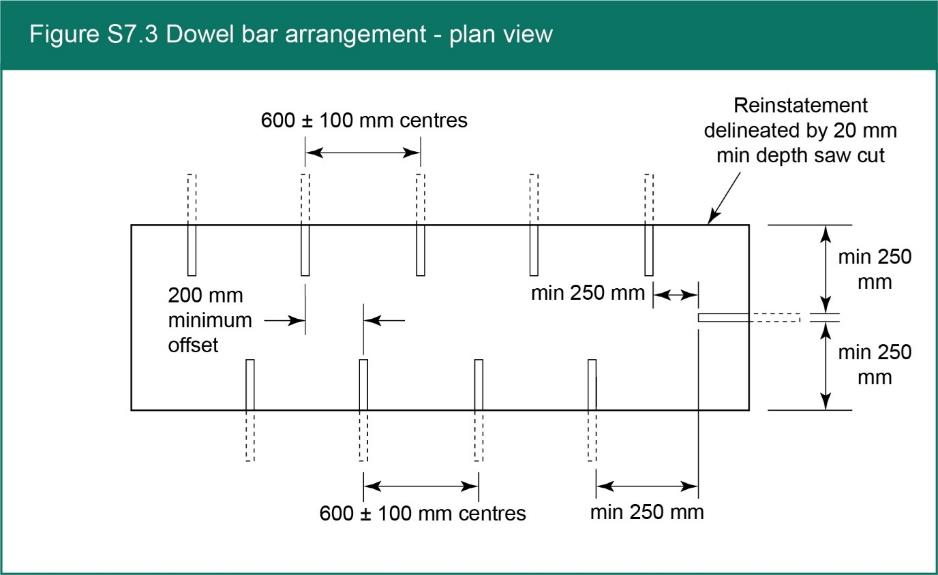
- In other openings or deep openings (S1.5.5 and S1.5.6 respectively), a row of horizontal holes must be drilled along the centreline of the exposed faces to provide a sliding fit for 20 mm or 25 mm diameter steel dowel bars as shown in Figure S7.3.
- S7.5.8
- The holes must be drilled at 600 mm ± 100 mm centres, with the holes along one face offset, relative to the opposite face by at least 200 mm when viewed from above; see Figure S7.3. The nominal hole depth must be equal to 50% of the dowel bar length ± 50 mm.
- S7.5.9
- The edge of the excavation must not be located within half of the dowel bar length plus 300 mm of a kerb, ironwork, transverse or longitudinal joints or another reinstatement unless the trim-line and surface reinstatement can be extended up to the feature in question, i.e. if 300 mm dowel bars are used, the minimum distance between the edge of the excavation and a kerb, ironwork, transverse or longitudinal joints or another reinstatement should be 450 mm.
- S7.5.10
- Dowel bars must be located at a minimum distance of 250 mm from the edge of the excavation, see Figure S7.3.
- S7.5.11
- The minimum dowel bar length is equal to the width of the reinstatement less 50 mm with a maximum dowel bar length of 400 mm. The first step in installing dowel bars is to place grout (cementitious or epoxy) into the back of each hole. The end of the bar that extends into the utility cut area should have a bond breaker applied to it to prevent bonding with the patch material. This bond breaker may be applied by the manufacturer or may be field-applied. Dowel bars must be clean, free of flaking rust, and epoxy-coated (or have equivalent anti-corrosion treatment) before installation.
Skip to main content
